After a month of development, I’m excited to share that I’ve built an ultra-low-cost, ultra-fast DIY IoT sensor network using Arduino, Raspberry Pi, and nRF24L01+. I initially tested the ESP8266 with its WiFi radio on, but it proved to be inefficient in terms of power consumption. So, I set out to find a better solution.
The ESP8266’s WiFi circuitry is quite power-hungry and takes a significant amount of time to connect. Every time it boots up or wakes up, the ESP8266 consumes at least 73mA for 5-10 seconds, which quickly drains the battery. As a result, the battery usually lasts only a couple of months with regular use.
As for those who struggle in Our cause, We will surely guide them along Our Way. And Allah is certainly with the good-doers.
Quran 29:69
Luckily, I discovered the 2.4GHz nRF24L01+ radio module, available for under $1 on AliExpress. Paired with the MySensors library and a Raspberry Pi Zero W as a gateway, it provides a far more cost-effective and efficient solution.
Objective
The goal is to utilize the nRF24L01+ module with the Raspberry Pi Zero W via the SPI interface to create a fast, lightweight IoT sensor network gateway. This setup enables seamless communication with other nodes and sensors equipped with the nRF24L01+ module.
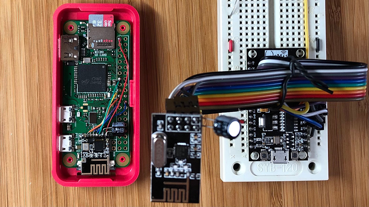
Hardware
- Raspberry Pi Zero W v1.1 (2017)
- nRF24L01+ (SMD)
- SanDisk Ultra 32GB microSDHC Card (UHS-1)
Software Stack
- DietPi v6.32.2
- Node-Red
- Mosquitto
- Netdata – UI for monitoring RPi’s system status
- MySensors library for the Node (Arduino) and the Gateway (RPi ZW)
Gateway Configuration
After setting up Node-Red, Mosquitto, Netdata, and Git on DietPi, the next step is to install the MySensors library on the Raspberry Pi.
git clone https://github.com/mysensors/MySensors.git --branch master
cd MySensors
./configure --spi-driver=BCM --soc=BCM2835 --my-gateway=mqtt --my-controller-ip-address=127.0.0.1 --my-mqtt-publish-topic-prefix=mysensors-out --my-mqtt-subscribe-topic-prefix=mysensors-in --my-transport=rf24 --my-rf24-channel=84 --my-rf24-pa-level=RF24_PA_MAX --my-rf24-ce-pin=15 --my-rf24-cs-pin=24 --my-rf24-encryption-enabled --my-signing=password --my-security-password=MySimplePassword --my-leds-err-pin=12 --my-leds-rx-pin=16 --my-leds-tx-pin=18
make
sudo make install
sudo systemctl enable mysgw.service
sudo systemctl start mysgw.service
For the IoT sensor network, we are using channel 84 (2.484 GHz), which is at the upper end of the 802.11 WiFi frequency spectrum. This choice minimizes radio interference and remains within safe national jurisdiction limits, effectively addressing both concerns.
Having enabled encryption, we now need to generate an AES key to ensure secure communication.
sudo mysgw --gen-aes-keyNow edit the config file and update the aes_key:
sudo nano /etc/mysensors.confNow restart the MySensor gateway daemon.
sudo systemctl restart mysgw.serviceSensor Node
I am using Arduino code on a NodeMCU to communicate with the Raspberry Pi gateway. Below is the code:
 /*
  * Sensor Node
  *
  * Simple binary switch example
  * Connect button or door/window reed switch between
  * digitial I/O pin 3 (BUTTON_PIN below) and GND.
  * http://www.mysensors.org/build/binary
  */

// Enable debug prints to serial monitor
#define MY_DEBUG

// Radio settings
#define MY_RADIO_RF24
#define MY_RF24_CE_PIN D3
#define MY_RF24_CS_PIN D8
#define MY_RF24_PA_LEVEL RF24_PA_MAX
#define MY_RF24_CHANNEL 84
#define MY_RF24_DATARATE RF24_250KBPS

// Enables SW backed signing functionality and encryption functionality
#define MY_SECURITY_SIMPLE_PASSWD "MySimplePassword"

#include <Arduino.h>
#include <MySensors.h>
#include <Bounce2.h>

#define CHILD_ID 3
#define BUTTON_PIN D2  // Arduino Digital I/O pin for button/reed switch

Bounce debouncer = Bounce();
int oldValue=-1;

// Change to V_LIGHT if you use S_LIGHT in presentation below
MyMessage msg(CHILD_ID,V_TRIPPED);

void setup()
{
   // Setup the button
   pinMode(BUTTON_PIN,INPUT);

   // After setting up the button, setup debouncer
   debouncer.attach(BUTTON_PIN);
   debouncer.interval(5);
}

void presentation() {
   // Register binary input sensor to gw (they will be created as child devices)
   // You can use S_DOOR, S_MOTION or S_LIGHT here depending on your usage.
   // If S_LIGHT is used, remember to update variable type you send in. See "msg" above.
   present(CHILD_ID, S_DOOR);
}


//  Check if digital input has changed and send in new value
void loop()
{
   debouncer.update();
   // Get the update value
   int value = debouncer.read();

   if (value != oldValue) {
      // Send in the new value
      send(msg.set(value==HIGH ? 1 : 0));
      oldValue = value;
   }
}
Looking ahead, my next project involves advancing to Low Power Long Range LoRa IoT technology. For a detailed look at how this represents an improvement over our current setup, check out my recent post on Low-Power Long-Range LoRa IoT Network. Stay tuned for more updates as I continue to push the boundaries of IoT innovation!
11th Safar, 1442 AH at Brooklyn, NY.

Leave a Reply