16th Ramadan, 1429 AH at Queens, NY.
After building the motherboard, I couldn’t wait to create my first robot. It took me less than a day to assemble this quick-and-dirty ghetto robot, which served as a pre-experimental project. Without any mechanical tools or a 3D printer at hand, I had to improvise. I repurposed a box that came with my NiMH battery charger as the chassis for my very first robot.
He originated the creation of humankind from clay. Then He made his descendants from an extract of a humble fluid.
Quran 32:7-8
Touch Sensor: Version 1
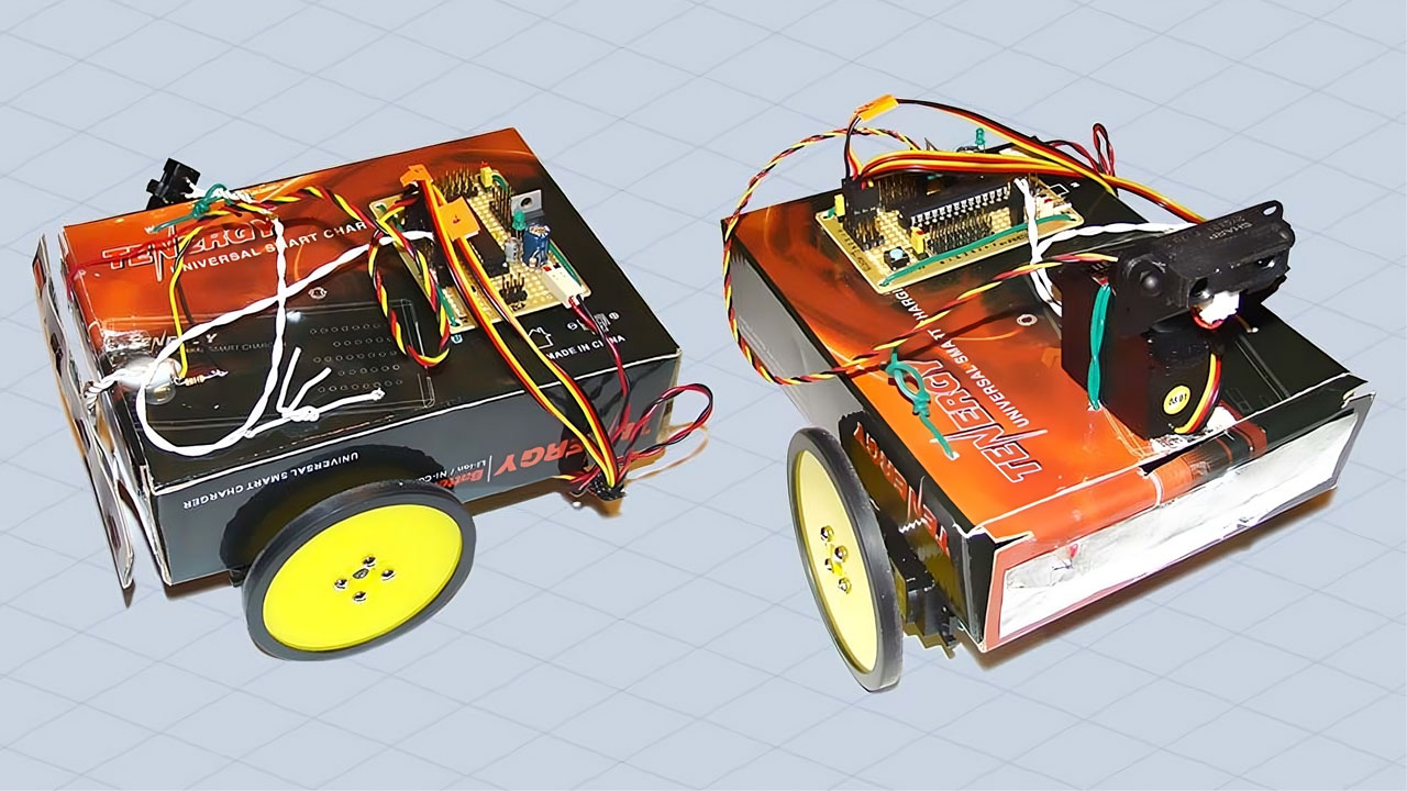
Here’s a close-up of my ghetto bot:

The only task assigned to it was to avoid obstacles. Using a simple touch sensor made from two pieces of aluminum foil, the robot could detect objects in its path and steer clear of them. This basic functionality was sufficient for a first program. I have bigger plans for my baby robot, so stay tuned and don’t forget to check the video of its movements.
Infrared Sensor: Version 2
With time, I improved my differential drive robot. Although I haven’t thought of a name for it yet, this upgraded prototype features an IR rangefinder that can detect objects within a range of 10cm to 80cm. I also added an extra servo to rotate the sensor left or right. Let’s take a closer look at the new prototype:

When the robot encounters an obstacle, it looks left and right, evaluating which side offers more space to navigate. It then turns in that direction and continues moving forward. Check out the video below to see how the robot maneuvers around obstacles.
It’s worth noting that during the initial creation of these robots, Arduino wasn’t widely known or available. I had to write the entire program in pure C, compile it using AVR Studio, and burn it into the ATmega8 chip using the AVRISP mkII In-System Programmer (ISP).

Take a closer look at the motherboard I created earlier. The board could be powered using a 6V adapter or five 1.2V NiMH rechargeable batteries. I used a low-dropout regulator, the LM2940T, to maintain the voltage at 5V. The board also offered two I/O Ports – a 6-bit PORT-B and an 8-bit PORT-D, and a 6-channel analog-to-digital converter (ADC).
Improved Design: Version 3
A few days after the initial build, I upgraded the design to version 3 of my robot. This version features a more refined structure and improved functionality.

Here’s a 3D sketch illustrating the new design of version 3. This sketch provides a visual representation of the improvements made to the robot’s structure.

For this version, I repurposed a gift box purchased from a dollar store as the chassis. Below is a picture of the box that served as the foundation for this version of the robot. The choice of material was both cost-effective and practical for my experimental setup.

Here’s a look inside the box. This image shows the internal layout and how the components are arranged within the chassis. It highlights the practical modifications made to accommodate the robot’s electronics, sensors, motors and batteries.

The final picture shows the fully assembled robot. This view captures the finished product with all components integrated and operational.

To optimize obstacle detection, I plotted data from the infrared sensor using MATLAB. This analysis helped me derive the equation needed to accurately calculate the proximity of obstacles, enhancing the robot’s navigational capabilities.
