13th Ramadan, 1432 AH at Queens, NY.
Many websites demonstrate how to make your own microcontroller board, but few of them describe the process in layman’s terms. Often, they emphasize either building the hardware or the software, rarely both.
In this article, I will show you how to build an AVR microcontroller board from scratch and write a simple program that blinks an LED.
Read! And your Lord is the Most Generous, Who taught by the pen — taught humanity what they knew not.
Quran 96:3-5
Components
You will need one of the following ATmega microcontrollers: ATmega8, ATmega168, or ATmega328. All three share the same pinouts, with the primary difference being their memory capacity. I recommend using the ATmega328, as it is the most recent and has the largest memory (2K SRAM, 1K EEPROM).
- ATmega MCU (I’m using the ATmega168)
- 16 MHz Crystal
- 78L05 Voltage Regulator
- Resistors: 1KΩ, 10KΩ
- Capacitors: 100μF 50V, 0.01μF, 2 x 22pF
- LED
- 6V – 12V Power Adapter (I’m using 9V)

Schematics

This simple design includes three external components:
Power Supply
The 78L05 provides a clean, regulated 5V power supply, which is required for powering the microcontroller.
External Clock
The quartz crystal generates a 16 MHz clock pulse, which is essential for the microcontroller’s operation.
ISP Pins
Pins 1, 17, 18, 19, GND, and VCC are used for programming the microcontroller using the AVRISP mkII programmer.
Programming
As is customary with embedded software, we will write a basic program in C that blinks an LED. First, let’s discuss the I/O ports. The ATmega microcontroller comes in a 28-pin DIP package. Pins 7, 20, 8, and 22 are used for the power supply. Four more pins: 17 (MOSI), 18 (MISO), 19 (SCK), and 1 (RESET) are used by the AVRISP for programming the chip. Pins 9 and 10 are used by the external clock (in this case, a 16 MHz crystal). The remaining pins are designated as digital and analog I/O ports.

Pins 14 through 19 are digital I/O ports, denoted as PB0 to PB5. Similarly, pins 2 through 6 and pins 11 through 13 are digital I/O ports, denoted as PD0 to PD7. Pins 23 through 28 are six ADC (Analog to Digital Converter) ports, denoted as PC0 to PC5.

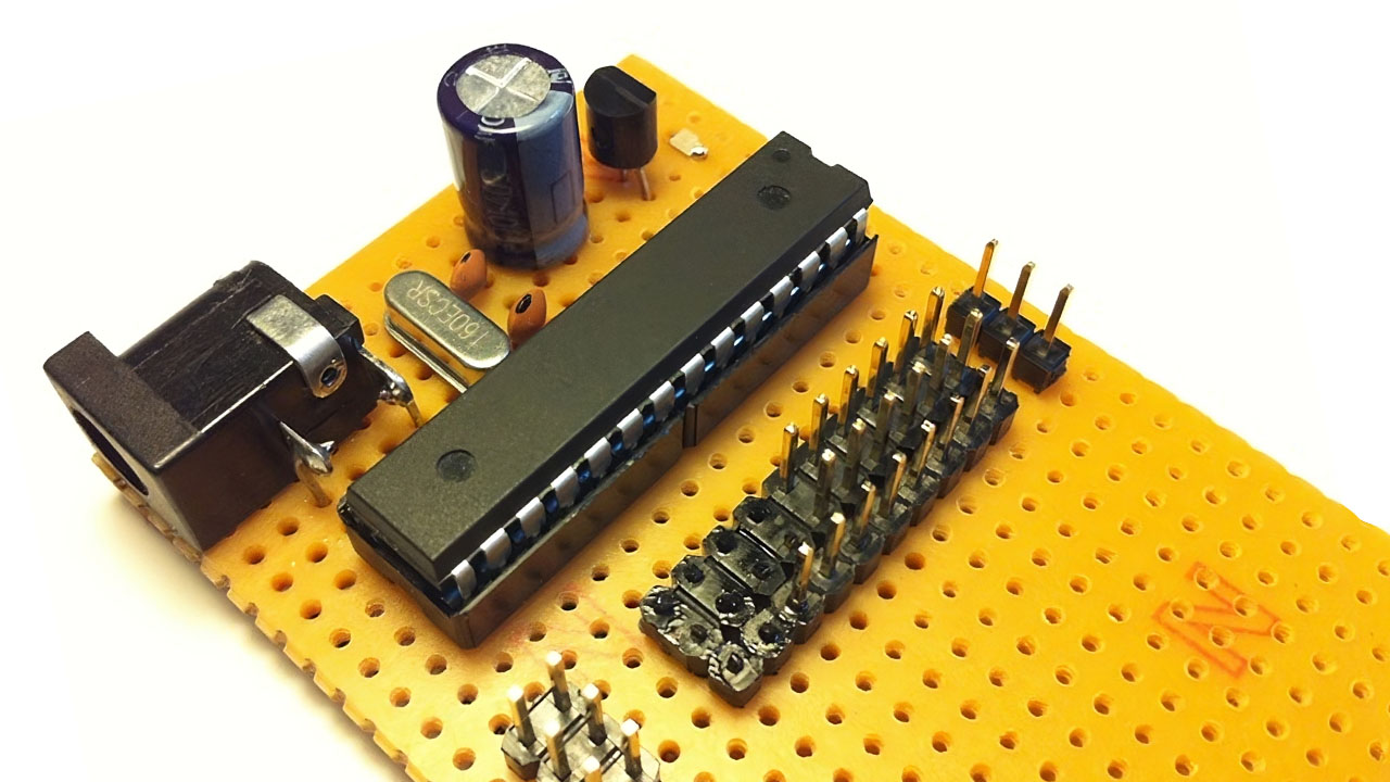
To wire up the AVRISP with the ATmega chip, connect the six pins: VCC, GND, MOSI (pin 17), MISO (pin 18), SCK (pin 19), and RESET (pin 1). In the picture above, you will see these six wires connected to the board.

Next, open AVR Studio 5 and write a simple blinky app. We will connect an LED to PORTD pin 3 (physical pin 5) on the ATmega chip, which will flash the LED once every second.
#include <avr/io.h>
#include <util/delay.h>

void setup()
{
    DDRD |= 0x08;  // Set PORTD bit 3 (PD3, physical pin 5) for output
}

void loop()
{
    PORTD |= 0x08;  // Turn on LED connected to PD3 (pin 5)
    _delay_ms(500); // Wait half a second
    PORTD &= 0xF7;  // Turn off LED connected to PD3 (pin 5)
    _delay_ms(500); // Wait half a second
}

int main(void)
{
    setup();
    for(;;) loop();
    return 0;   /* never reached */
}