13th Shaban, 1429 AH at Queens, NY.
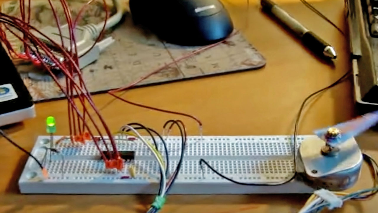
This project marks my first foray into working with stepper motors, where I utilized the NIPPON PF35T-48L4 unipolar motor. I controlled this motor from a PC using the Parallel Port (LPT1, DB25). For amplification of the input current from the port, I employed a ULN2003A IC, which features a 7 Darlington Transistor Array. This 16-pin IC can handle TTL input and support output loads with voltages up to 50V. I wrote a simple program in Visual Basic 6, leveraging the inpout32.dll driver.
And He is the One Who created the day and the night, the sun and the moon—each traveling in an orbit.
Quran 21:33
Below is a schematic of the ULN2003, the unipolar stepper motor driver IC:

It is recommended to connect a 6.2V zener diode between the power supply and VDD (Pin 9) on the chip to absorb the reverse (or “back”) EMF generated when the motor coils are switched off.
To rotate the motor counterclockwise, the step sequence sent to the parallel port is as follows:
STEP-1   0001     1
STEP-2   1001     9
STEP-3   1000     8
STEP-4   1010    10
STEP-5   0010     2
STEP-6   0110     6
STEP-7   0100     4
STEP-8   0101     5
Here is a live video demonstrating the motor in action:
